Scale modeling III
The final task is to run the missing wiring responsible for controlling the mirror folding motors.
As I mentioned in an earlier post, it’s really handy to have a spare wiring loom from the left door to use the original pins. Additionally, you’ll need copper wire. I bought 10 meters of 1mm double-core wire, which was probably a bit of an overkill. You can easily divide that in half, so 5 meters should be just enough. The 0.5mm diameter is closer to the original as well. The double-core wire works well because you need to run two wires, making it quite convenient.
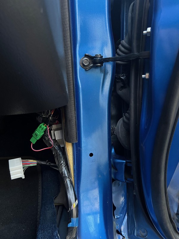
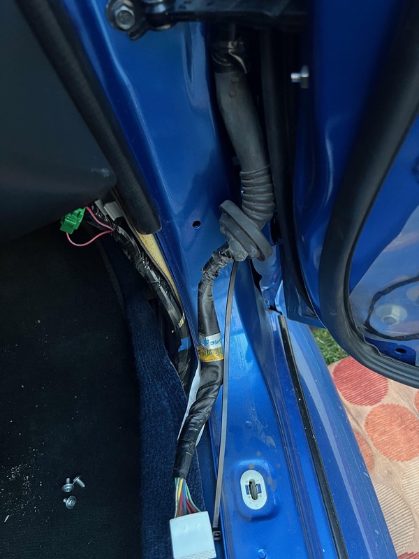
Start by removing the door cards. Next, disconnect the door wiring, which is hidden under the plastic cover at the edge of the carpet. After disconnecting the wiring, you need to remove the rubber boot that connects the door to the rest of the car.
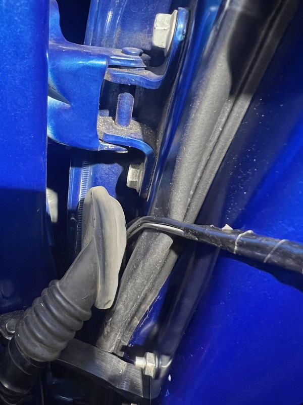
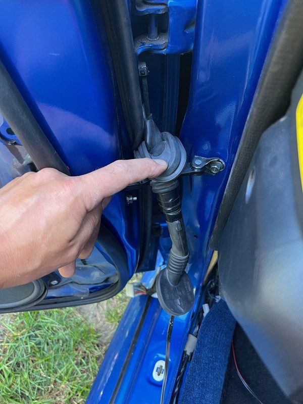
Pulling out the rubber boot will reduce the number of curse words per minute shouted during the attempts to push the cables through. The easiest way is to use a long zip tie, which you first pass through the rubber, then attach the wires to it:
The top part of the rubber trumpet should be carefully cut a few centimeters above the bulge so the wires can come out. For the right doors, I passed the zip tie from the bottom, and for the left doors, from the top, and I think the latter is much easier:
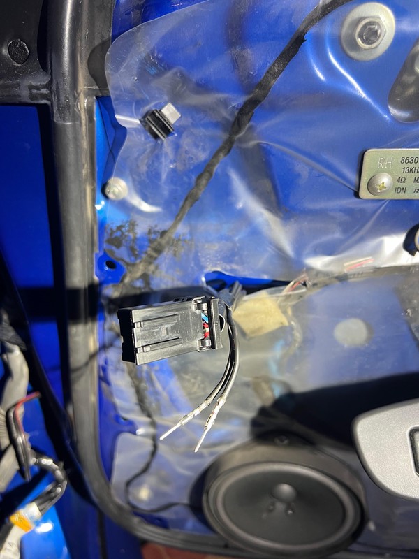
There are fewer tasks for the right door. The only thing you need to do here is to crimp the wires with pins and insert them into the correct slots in the plug (more on this in a moment):
I hid the wires from the right door under the carpet and ran them to the spot where the original wiring leaves the cabin and heads toward the door. For the driver’s side, we need to add pins both for the mirror connector (just like the passenger side) and for the switch:
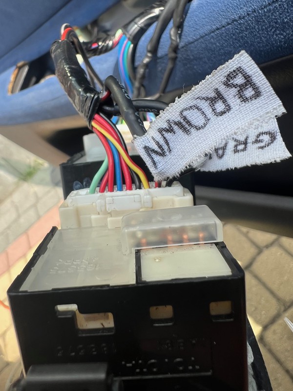
For the car archaeologists of future, I’ve labeled the wires with their intended colours:
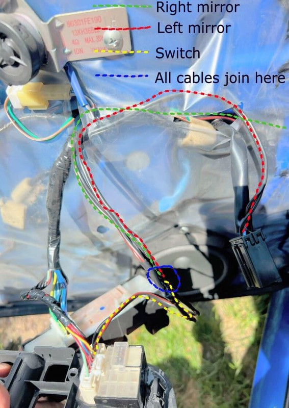
Everything needs to be connected, that is the wires from the right mirror should be joined with those from the left, and this set should be connected to the branch that goes to the switch. It should look something like this:
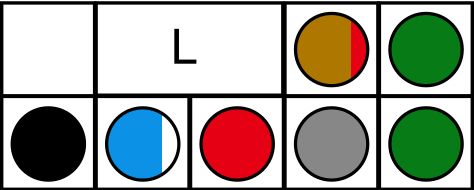
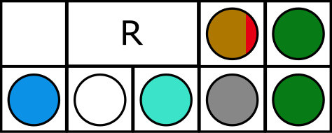
The last unknown is the pin configuration in the connectors, for the model with heated mirrors:
- Left:
- Right:
The brown-red and gray wires control the folding, and the green wires are responsible for heating. The rest are standard, like in any other model.
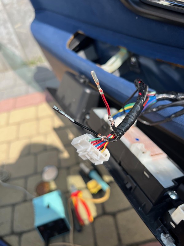
Finally, the switch — I added the first two wires from the left hand side:
The moment everyone has been waiting for:
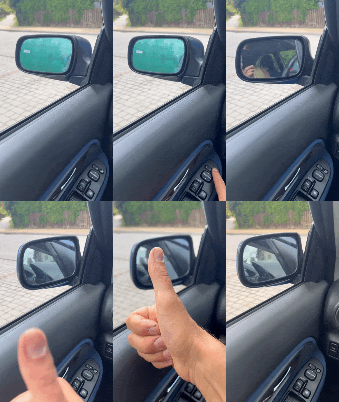
Tada!
