Latent Heat of Vaporization II
For a moment, it looked like this:
But I got it under control fairly quickly.
So, I got the urge to tinker. I’ve been thinking about creating an automatic intercooler water spraying system for quite some time. Not that I really needed it, but because it seemed like a fun project. I did a bit of digging on the internet and found this post where Charlie explains everything really well. I’ll just briefly cover the most important points here.
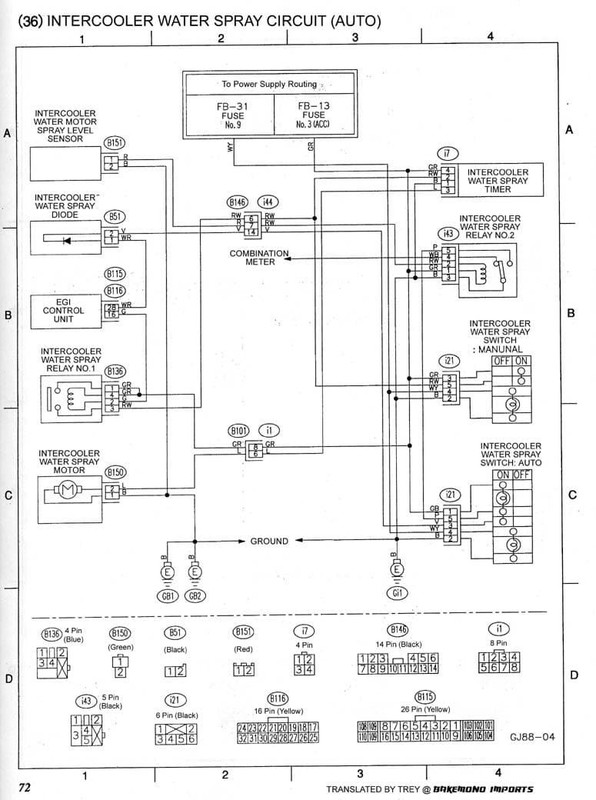
First of all, the wiring diagram for the JDM intercooler water spray system (from Charlie’s site):
B146, B101, B115/116, and B51 can be immediately ignored, because those are connectors, the EGI controller, and a diode (so the controller doesn’t throw a fault). I remember talking to Piotr from MapTek once, and he said he based his system on the ECU, but that would be a bit much for me, so I opted for a pressure switch. This brings us nicely to the necessary parts:
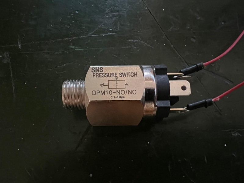
- Pressure switch: SNS Pressure Switch QPM10. I got one with both NO and NC terminals, but only NO is strictly needed. It’s rated from 0.1 to 1 MPa, and I plan to set it at the lower limit, so the spray activates at 1 bar of boost. There’s a small hex adjustment between the pins that controls the pressure. Since I have a boost gauge installed on the dash, I should be able to verify the values.
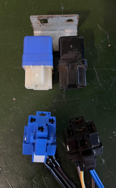
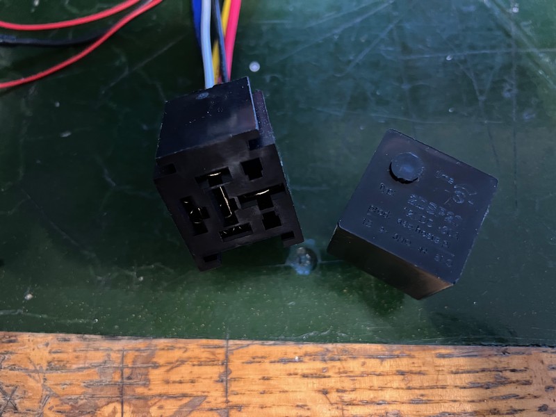
- Two relays: 2523079972 and 2523079971 (5-pin and 4-pin, respectively), quite common and not only used in Subarus. It’s important to buy the relay set with the harness. I even managed to get a mounting board.
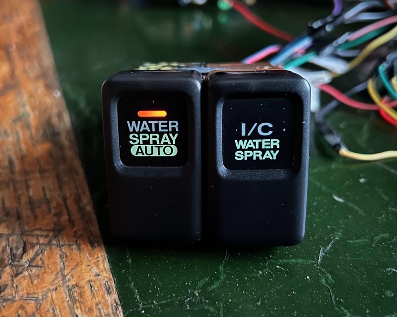
- WATER SPRAY AUTO switch: This might be the hardest part to find, as they’re not very common. I got mine from the UK.
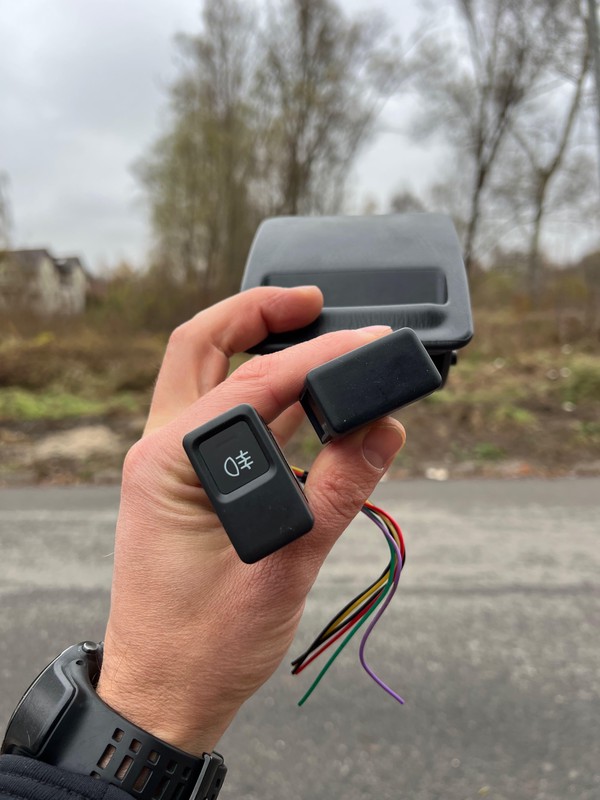
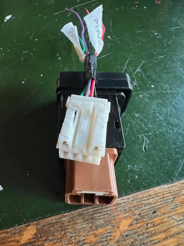
Unfortunately it came without the connector, so I had to butcher the one from fog light switch.
These are the essential parts, assuming you’re modifying an existing STI system. If not, you’ll also need:
- 2-second timer relay: I only needed this for testing, so I didn’t buy the OEM one but the cheapest available, a 2DSP20. It has an adjustment screw hidden behind a cap which sets the delay time.
- I/C WATER SPRAY switches.
The goal of this stage was to create a prototype on my desk, meaning all the functionality there but in a more manageable form. I didn’t want to do it directly in the car right away, as it would involve more risk of things going sideways, bad weather, and a lot of connectors to unplug. So, I needed a few more parts:
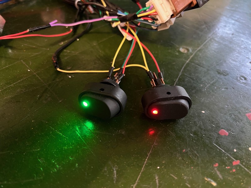
- 2 toggle switches: one for controlling the backlight (green), the other for simulating low-water-level sensors in the reservoir (red).
3 LEDs: One to represent the pump, one to indicate low water level (in the car, this information is displayed on the instruments cluster), and the last one to show system spraying, which I plan to use in the final version.
Some connectors and wires.
Working principle.
In normal mode, every press of “I/C WATER SPRAY” triggers a 2-second shower, or the pump running dry since the low-water-level signal is completely ignored in this mode. The automatic mode is more sophisticated. Pressing the switch turns on the button’s backlight and sets the system to “standby” mode, where it awaits the set boost value (1 bar). Once this is reached and if the low-water-level sensor is not triggered, a signal is sent to the timer relay, and from there, it operates just like in the normal mode. The two relays, which aren’t present in the basic version, handle the low-water-level signal and ensure that the spray isn’t activated if there’s insufficient water.
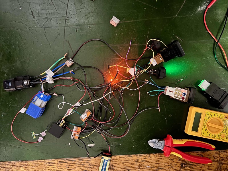
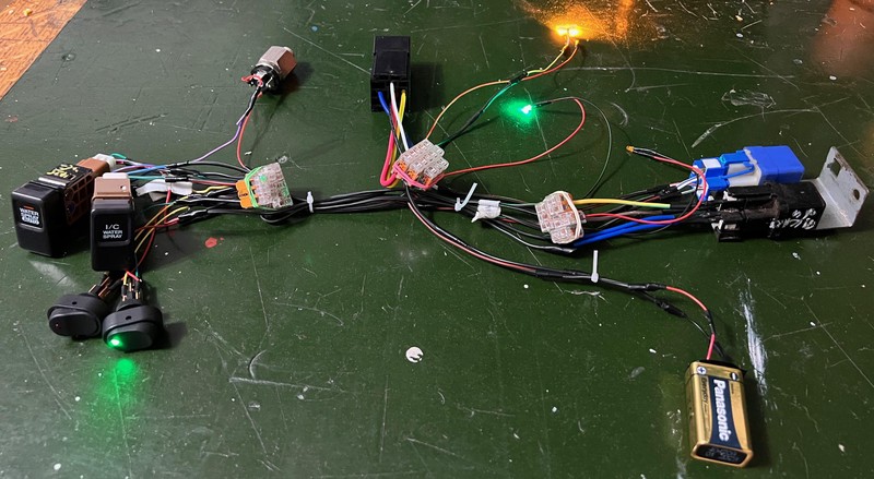
Here’s how it looks assembled on the desk:
Everything works: backlit buttons, the low-water-level indicator, and the handling of that signal. Now all that’s left is to wait for spring and install this desk prototype into the car.
